ECE Communications Project: Search and Pick a Seat (SPAS)
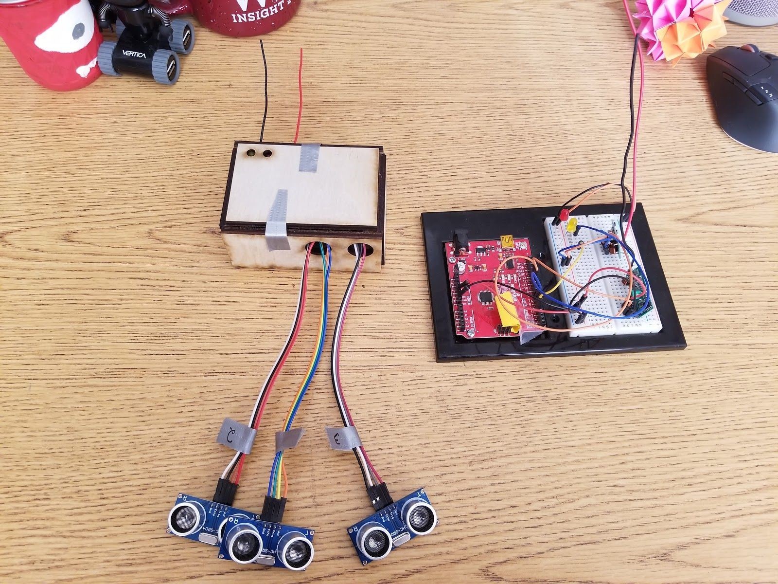
Our IoT system has multiple sensor nodes, that consisted of ultrasonic sensors (Transistor-Transistor Logic) connected to an Arduino Nano microcontroler (3 for each MCU). The sensor node microcontrollers were responsible for processing the resulting sensor data and utilizing the 433MHz RF front-end receivers and tranceivers (Amplitude-Shift Keying) that were integrated to commmunicate with an aggregator node. Antennas were also included for both the sensor and aggregator nodes to propagate signals at greater distances, therefore solving any attenuation/path loss that the signals could encounter, while also being careful not to overamplify the signal as this could cause interference with other signals. The aggregaror node also had the 433MHz RF front-end receivers and tranceivers, which were connected to an Arduino Uno. For the MAC Layer, we framed a datagram and added overhead to the transmitted signals coming from the sensor nodes so the aggregator node can filter out the received data into the right channels. Furthermore, we used the Time-Division Multiple Access (TDMA) channel access method to handle multiple sensor nodes communicating with one aggregator node. In our case, only one sensor node was able to transmit during each time slot. The aggregator node served as a master that called on the sensor node name that it wanted to communicate with. Then, the sensor node sent out the frame to the aggregator and once it finished processing the data, the aggregator node called on the next sensor node it wanted to communicate with. Additionally, the system was able to check for corrupted files and data not received with a parity checking process. Finally, the results regarding cubicle occupany are periodically posted over Internet to our smartphone application. For more details, please take a look at the source-code repository that also includes our Final Report (repository is on my GitHub page and a link to it can be found on the Portfolio page of this website under the corresponding project). Slideshow Gallery
1 / 5

2 / 5

3 / 5
4 / 5

5 / 5